Microcontrollers and programmable logic controllers (PLCs) are used to monitor and control many types of sensors and devices on a wide range of industrial equipment. One commonality among these applications is that the controller always needs a way to connect with the input/output (I/O) signals physically and electrically. This usually takes the form of a screw terminal, push-in-design (PID) terminal, or perhaps a connector—which is the point where the on-board I/O electronics transition to a wire running to a field device.
This signal transmission and distribution interface can be achieved in several ways, but it typically takes up a lot of space compared with just the controller itself, and the interface also represents a point of failure. As systems become more complex with a greater amount of automation and more I/O points, the need for compact and reliable interface methods becomes apparent. This article discusses the interface module features designers should look for, and the benefits of choosing a universal system.
Signal Types
Most industrial systems rely on a small variety of signal types. Discrete (on/off) signals are typically 24VDC (although in some cases may be as high as 120VAC or as low as 5VDC), and they are almost always fairly low current. Analog signals usually operate in the range of 4-20mA or 0-10VDC. There are also some specialized signaling levels for thermocouple and RTD temperature measurement, millivolt strain gauges, and others. In summary, a large amount of industrial I/O signaling needs are for low voltage and current.
However, there are still cases where higher voltage and current switching may be needed, or electrical isolation is necessary, such as for operating motor starters, variable frequency drives, large solenoids, and electric heaters. In these cases, relays can be used as the interface point since they are designed to use a small switching signal to operate a different—and often higher power—output signal, while also providing electrical separation and isolation. Additional complications arise because relay signals can be NPN or PNP, with several different types of contact form factors. Installing many relays into a control panel is costly in terms of labor and space efficiency, and they can be difficult to troubleshoot and maintain.
One final point is that most digital controllers are designed compactly, and to achieve this all the I/O signal points are condensed into a connectorized format. Some typical connector types on-board controller or I/O modules include:
- IDC (14-pin, 20-pin, 26-pin, 30-pin, 34-pin, 40-pin)
- D-Sub (37-pin, 44-pin)
- MDR (50-pin, 68-pin, 100-pin)
- Terminal Blocks
Designers need a universal and efficient way to connect controllers and I/O modules of all types with a wide variety of field signals.
Getting Connected
The answer can be found in a family of flexible interface modules designed to work with any controller and I/O platform, while providing connectivity options for all types of signals (Figure 1).
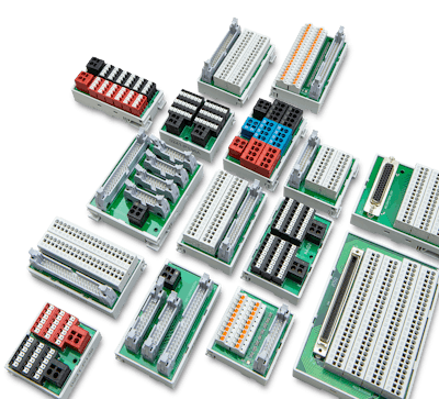 Figure 1: Interface modules, like the Dinkle models shown here, provide a universal and standardized way for OEMs and designers to obtain safe and reliable controller I/O connectivity.Dinkle International
A single wire harness provides the connection between the controller I/O and the interface module. This connection transfers a number of high-density signals, typically from 2 to 40, to individual points suitable for wiring to field devices. Instead of tediously installing individual connections, terminal blocks, and relays into a control panel—users can fabricate automation system control panels quickly and systematically in the most compact space possible—while avoiding errors.
These interface module systems are universal and work with any controller, such as those from Siemens, Allen-Bradley, Mitsubishi, Delta, Omron, Keyence, Panasonic, and more. They also work with all signal types, so control panel designs can always use the same termination systems, no matter what model of controller is used.
When choosing an interface module system, designers should look for additional usability features. Modules should have provisions for clear marking and color coding to assist with accurate field wiring, and they should be DIN rail mounted for flexible and reliable installation. Termination points outfitted with LED status indication are particularly useful for showing operation and helping with troubleshooting. Cables should be industrial-grade, with shielded and unshielded options to support different applications. Where possible, I/O points should be reverse-polarity protected.
Note that the terminal block where a field wire is landed represents the highest risk for failure, so extra attention is warranted at this point. Therefore, all terminal block and materials should be UL1059 recognized and IEC60947 approved.
Traditional screw-cage terminal blocks have been the norm for many years. Today, most users are finding that newer push-in design (PID) terminal blocks are the superior choice due to more compact size, faster installation, and improved long-term reliability. A high tensile strength stainless steel clip holds each wire securely and resists vibrations, even low frequency micro-vibrations, ensuring connection stability.
Application Example
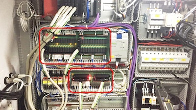
One OEM of packaging manufacturing equipment faced significant space constraints for installing a Mitsubishi Melsec-Q Series PLC in a control panel. The PLC used two 32-point input and two 16-point output I/O expansion modules connected to equipment sensors and actuators (Figure 2).
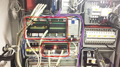 Figure 2: The connection density and efficiency provided by Dinkle signal and relay interface modules makes it easier for equipment OEMs to design and fabricate control panels.Dinkle International
By using two signal and two high-density relay interface modules with IDC-to-IDC pre-assembled wiring harnesses, the OEM was able to implement the most compact installation footprint possible while saving installation and wiring time, yet still providing good serviceability, especially with the LED indicators.
Universal interface modules provide up to 30% panel space savings and reduced need for parts inventory, along with up to 70% labor savings due to the use of PID terminals.
For any equipment or industries where microcontrollers and PLCs interface with and operate field devices, there is a need for connection solutions that are compact, flexible, universal, and reliable. Interface modules deliver all these benefits, while providing reliable and supportable connectivity.
About the Author
 Matt Hou, Sales Engineer, Dinkle International


